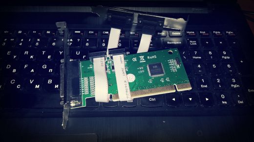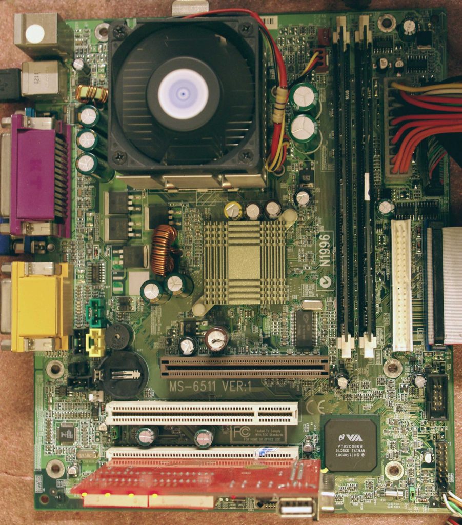
Попала в руки данная материнская плата. Поскольку это старый OEM – информации о ней на сайте производителя нет. На сайте NEC также пусто, за исключением вот такой странички из WaybackMachine. Решил причинить миру немного добра, собрал все о ней воедино, и сделал дамп BIOS.
Front Panel:
Front USB:
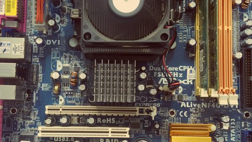
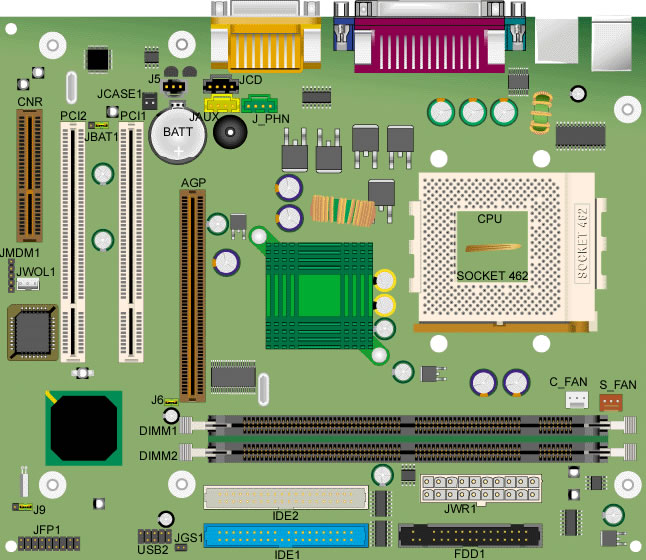
Общая схема платы, а также описание коннекторов и джамперов (с бывшего оф.сайта):
Important Note:
There are two versions of the Explorer motherboard, depending on the type of CPU it supports. Part numbers of Explorer motherboards can be 683623xxxx or 683767xxxx.
- 683623xxxx motherboards support AMD Athlon and Duron processors.
- 683767xxxx motherboards support only AMD Duron processors.
For detailed information on how to identify the type motherboard check the section Athlon/Duron processor identification. |
Motherboard Configuration (jumper settings)
- Clear CMOS jumper (JBAT1)
- BIOS Configuration Access (J9)
| Setting |
Clear CMOS jumper (JBAT1) |
![]() |
| 1-2 on |
Normal operation (default) |
| 2-3 on |
Clear current BIOS default settings |
| Setting |
Front Side Bus speed |
|
| 1-2 on |
133 MHz: Supports 266 MHz FSB Athlon at 1333 MHz maximum and 266 MHz FSB Athlon XP 2000+ maximum |
| 1-2 off |
100 MHz: Supports 200 MHz FSB Duron at 1300 MHZ maximum and 200 MHz FSB Athlon at 1300 MHz maximum |
| Setting |
Bios Configuration Access (J9) |
![]() |
| 1-2 on |
Normal operation (default) |
| 2-3 on |
Access BIOS maintenance panel |
| none |
BIOS recovery |
Note: When jumper J9 is set to position 2-3, you will find a new option in the BIOS Setup: Maintenance. Here you can clear all user and supervisor passwords (press <Enter> and confirm the operation).
|
Internal Connectors
| Denomination on drawing |
Name |
Type |
| CNR |
Communications Network Riser |
Standard CNR slot
| Note: The CNR connector is a combo slot with the bottom PCI connector. Use either the CNR or the PCI connector; you cannot use both connectors at the same time! |
|
| PCI 1, 2 |
PCI connectors |
Standard PCI extension slots
| Note: PCI 2 is a combo slot with the CNR connector. Use either the CNR or the PCI connector; you cannot use both connectors at the same time! |
|
| AGP |
Accelerated Graphics Port |
Standard AGP connector |
| DIMM 1 |
Bank 0/1 DIMM socket |
168-pin standard socket |
| DIMM 2 |
Bank 2/3 DIMM socket |
168-pin standard socket |
| IDE 1 |
Primary IDE connector |
40 (2×20) pin header |
| IDE 2 |
Secondary IDE connector |
40 (2×20) pin header (white) |
| FDD1 |
Floppy drive connector |
34 (2×17) pin shrouded header |
| CPU |
CPU socket |
Socket 462 |
| JWR1 |
Power connector |
20-pin keyed connector |
| JAUX |
Aux Audio |
4-pin shrouded header (yellow) |
| J_PHN |
Modem audio |
4-pin shrouded header (green) |
| JCD |
CD audio header |
4-pin shrouded header (black) |
| J5 |
SPDIF |
3-pin shrouded header (black) |
| C_FAN |
Power fan connector |
3-pin shrouded header |
| S_FAN |
System fan connector |
3-pin shrouded header |
| BATT |
Battery socket |
Lithium coin battery socket |
| WOL1 |
Wake On LAN connector |
3-pin shrouded header |
| JMDM1 |
Not used |
5-pin header |
| JWOR1 |
Wake On Ring connector |
2 x 5-pin header |
| USB2 |
Front USB header |
2 x 5-pin header (minus 2-pin) |
| J9 |
BIOS configuration access jumper |
3-pin jumper |
| J6 |
Front Side Bus speed |
2-pin jumper |
| JBAT1 |
Clear CMOS jumper |
3-pin jumper |
| JCASE1 |
Chassis intrusion header |
2-pin header |
| J4 |
Not used |
5-pin header |
| JGS1 |
Not used |
2-pin header |
| JFP1 |
Front Panel header |
2 A?- 9-pin header (minus 1 key) |
|
|